
Part 1: OSPF (IPv4) - Connecting 2 Instances of VyOS and pfSense Together

This is part 1 of 2 of configuring multiple networks that can communicate with each other through OSPF.
Introduction
How much do you know computer networking? Do you know how subnetting works? What about IP addresses? Do you know how routers and switches work? Do you have a homelab and do you know what a homelab is? If you answer yes to all of the questions and you want to expand your knowledge of networking, this article is for you. Yes, I'm targeting audience that have a good knowledge in networking. This is even for those with lack of certificates such as CompTIA A+, Network+, and Security+, and even for those without a degree! Well, why don't we delve right into it, shall we? If you are Network+ certified, you must know that OSPF is a dynamic link-state protocol that allows the two or more private networks to talk to each other. If you have a consumer router such as Netgear or Linksys, this article is only for the pros!
Also, my article covers the use of virtual machines and networking bridging, so I'm going to assume you know how to set them up. I'm using Ubuntu Server 20.10 as my Linux home server that runs KVM (Kernel-based Virtual Machine). Virtual machines are what enables a computer to run inside a computer and network bridging behaves similar to a network switch. And because of that, I'm also going to assume you are familiar with the Linux command line.
Now buckle your seatbelt because this article is going to be a very long one.
Table of Content
- Introduction
- Table of Content (You are here.)
- Glossary Terms and Notes
- Scenario
- How I Setup The Environment
- Downloads
- Ready to Configure Virtual Machines for OSPF?
- Configure the First Instance of VyOS
- Are We Done with VyOS?
- Summary
- I Welcome Your Feedback!
- Revisions
Glossary Terms and Notes
- IPv4
- Internet Protocol version 4; a 32-bit addressing scheme in a form of
a.b.c.d(0 to 255 for each octet) - OSPF
- Open Shortest Path First is a dynamic link-state protocol.
- NAT
- Network Address Translation: used to provide public-to-private IP address translation when an ISP can only assign a single public IP address. IPv6 (128-bit addressing scheme does away with NAT because each device can be assigned a public IPv6 address).
- KVM
- Kernel-based Virtual Machine for running virtual machines in a home server or desktop. A virtual machine is akin to putting a computer inside a computer each running its own operating system.
- Router
- A router connects one or more networks together and even connects the network to the Internet. A router can act as a default gateway if an IP address falls outside the list of network the router is connected to.
- Switch
- A network forms a star topology by connecting more than one host (a computer, printer, home theater receiver, etc.) to a central switch. If an IP address falls outside the subnet, a switch can forward a packet to a router.
You can learn a lot about computer networking by going through the tutorial. Basic networking is beyond the scope of my article.
(Return to Table of Content.)
Scenario
You work at a company called "GalaxyTech" that specializes in building PCs and servers. Your company has three buildings. The two buildings connect to a central building through fiber. The central building has a fiber connection to the Internet Service Provider. Each of the three buildings have a purpose:- Central building: Office rooms, IT department, web development, sales department, and accounting.
- Manufacturing facility: for building computers and servers, has rooms for office spaces, and IT department.
- Warehouse building: warehouse, shipping, office rooms, and IT department.
Your job is to travel to three buildings and get networking setup. An ISP has provided a set of IP addresses within a subnet, which is 172.24.19.0/29. For the purposes of the article, I'm using 172.24.19.0/29 as a private subnet. 172.16.0.0/12 is part of RFC 1918 private addressing scheme. Plus, the three networks are going to be as follows:
- Central building: 10.249.0.0/24
- Manufacturing facility: 10.249.1.0/24
- Warehouse building: 10.249.2.0/24
The three networks should be able to talk to each other. Note, however, this is going to be a very simple scenario. In the production environment, it is important to split a single subnet into a smaller subnet and segment them into different networks. Plus, different networks should not talk to each other and pinging should not be allowed for security reasons. But in this article, I am keeping it simple.
(Return to Table of Content.)
How I Setup The Environment
My computer and server both have 2.5Gbit Ethernet adapters installed. There is no switch involved as I cannot afford a managed 8-port switch that supports VLANs at the time of writing, so I simply have a straight cable that connects from my computer to my server. And because I'm running Ubuntu Server 20.10 in my home server, I want to share how my home network is configured (/etc/netplan/00-installer-config.yaml).
# This is the network config written by 'subiquity'
network:
  version: 2
  ethernets:
    enp3s0f1:
      dhcp4: no
    enp4s0f0:
      dhcp4: no
    enp4s0f1:
      dhcp4: no
    enp7s0:
      dhcp4: no
  bridges:
    ...
    ethbr10: # Computers, Smartphones, etc.
      interfaces:
      - enp7s0
      - enp4s0f0
      - vlan10
      dhcp4: no
      addresses:
      - 172.20.1.1/26
    ethbr10_2400:
      interfaces:
      - vlan2400
      dhcp4: no
    ethbr10_2401:
      interfaces:
      - vlan2401
      dhcp4: no
    ethbr10_2402:
      interfaces:
      - vlan2402
      dhcp4: no
    ...
    ethbr10_2409:
      interfaces:
      - vlan2409
      dhcp4: no
    ethbr10_2419:
      interfaces:
      - vlan2419
      dhcp4: no
    ethbr10_2429:
      interfaces:
      - vlan2429
      dhcp4: no
    ethbr20: # Home Automation, Wired
      interfaces:
      - enp4s0f1
      dhcp4: no
      addresses:
      - 172.20.5.1/24
    ...
  vlans:
    vlan10:
      id: 10
      link: enp3s0f1
      dhcp4: no
    ...
    vlan2400:
      id: 2400
      link: ethbr10
      dhcp4: no
    vlan2401:
      id: 2401
      link: ethbr10
      dhcp4: no
    vlan2402:
      id: 2402
      link: ethbr10
      dhcp4: no
    ...
    vlan2408:
      id: 2408
      link: ethbr10
      dhcp4: no
    vlan2409:
      id: 2409
      link: ethbr10
      dhcp4: no
    vlan2419:
      id: 2419
      link: ethbr10
      dhcp4: no
    vlan2429:
      id: 2429
      link: ethbr10
      dhcp4: no
My home server is equipped with a 4-port Gigabit networking card, a built-in NIC in my motherboard, and a 2.5Gbit networking adapter. The motherboard's built-in NIC is not in use. My computer's IP address is 172.20.1.8, which is part of a /26 subnet. I do have a couple of VLANs setup in my desktop computer as well. But instead of Ubuntu, I'm running Arch Linux, which is for experienced Linux users such as myself. So back to the Netplan config file, Netplan seems to be exclusive to ubuntu and is not available in other Linux distributions such as CentOS and Debian. All of the interfaces have DHCP set to no so this is more like a router that connects multiple networks together and pfSense is a router distribution that runs in a virtual machine. pfSense has an IP address of 172.20.0.2 and resides in ethbr0 bridge interface which is not shown here in order to keep it short. My computer, laptop, and smartphone resides in ethbr10. Each VLAN has an ID and is linked to a specific bridge interface, which in this case, ethbr10. Then, each bridge is specifically bridged to each VLAN. So, the way it works is this: ethbr10_2400 is linked to vlan2400 with a VLAN ID of 2400, vlan2400 is linked to ethbr10, and ethbr10 is bridged to multiple interfaces including a VLAN interface with an ID of 10. Sure, my networking is very complex, but that is part of the homelab!
As for my desktop computer, I use Network Manager for networking. Here's what it looks like:

In order to create virtual machines, I wanted to do so as a user instead of root. To do that, I added a user called kvmguests and added libvirt as a group.
sudo apt install acl # If not already installed.
sudo useradd -m -c "KVM Guests" -G libvirt kvmguests
sudo passwd kvmguests
sudo setfacl -R -m d:u:kvmguests:rwX /vm/kvm/
sudo setfacl -R -m u:kvmguests:rwX /vm/kvm/
The acl package provides the setfacl and getfacl. For those who do not know, ACL stands for "Access Control List" which grants or denies read/write/execute permissions for files and directories. /vm/kvm contains two directories: iso and img. The iso directory is for holding installation images and img directory is for holding virtual machine disk images.
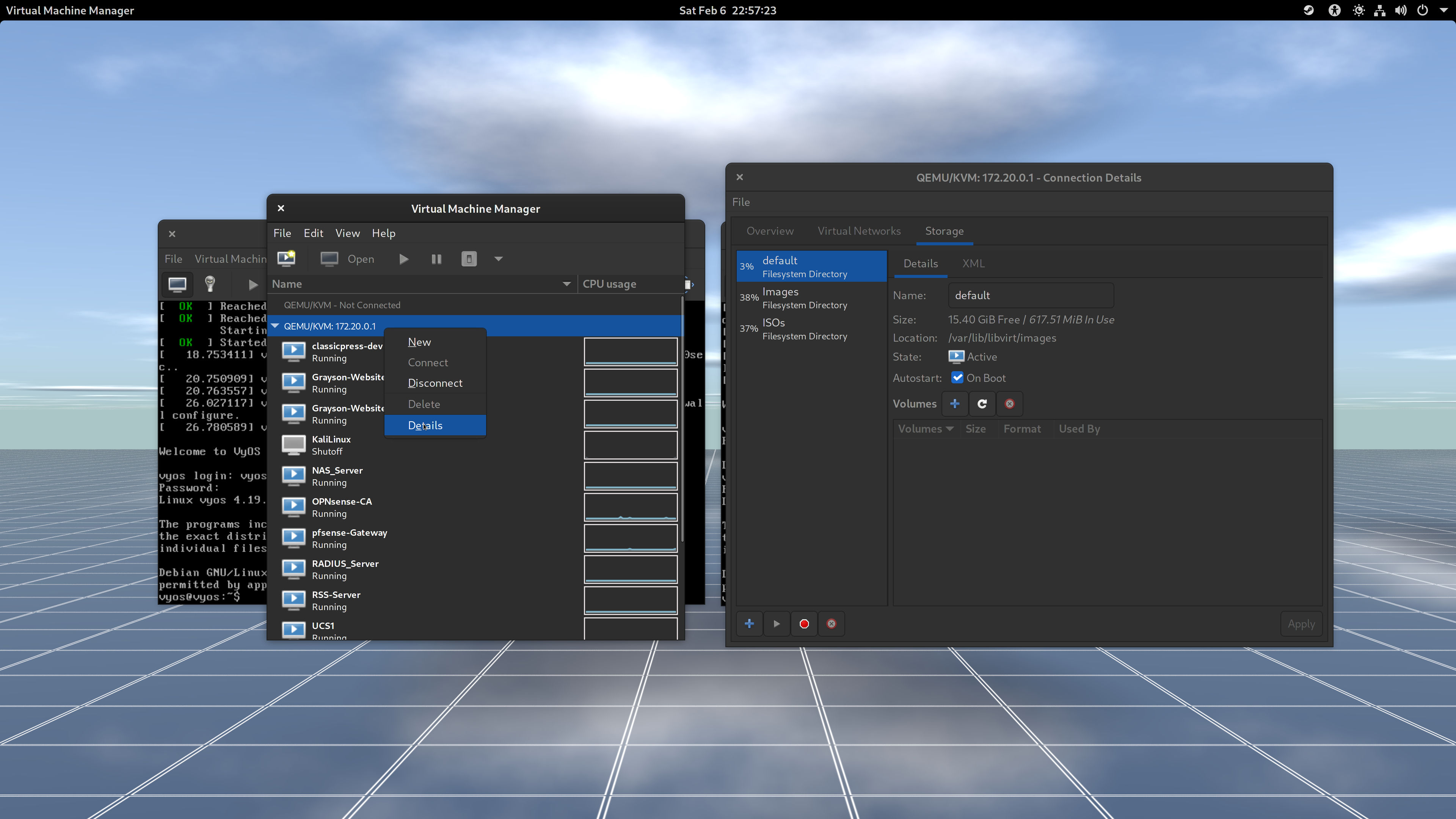
So, to get to the list of storage pools, right-click where it says "QEMU/KVM," click Details, and in the Connection Details dialog box, click Storage. You can add whatever storage pool you need. I suggest keeping the installation images separate from disk images. This helps keeps it organized.
(Return to Table of Content.)
Downloads
For VyOS, you'll want the rolling release as the LTS release requires a purchase of a subscription.
Ready to Configure Virtual Machines for OSPF?
Okay, so you got your virtual machine environment and your network all setup and ready to go, so it's time to get your virtual machines up and running. For those who have eyesight, you can click in the checkbox to show the list of images. For blind users, I do not know how this is going to work for you when it comes to exiting out of the virtual machine window using your keyboard. You could make use of serial connection by deleting the video display when you customize the installation before starting a virtual machine. However, I've ran into problems when trying to get the pfSense installer image up and running. Please accept my apologies for not being of much help if you rely on your screen reader. Anyway, let's get going.
Images for Installing and Configuring Virtual Machines


Prerequisite
First, enable virtualization extensions in your computer's BIOS. This will depend on what motherboard/PC/laptop you use. If you can't see the screen, ask someone to help you navigate around the menus in the BIOS screen.
If you do not have virt-manager installed in your desktop, use your package manager to install virt-manager.
- Debian and Ubuntu:
apt update && apt install virt-manager - Fedora:
dnf install virt-manager - OpenSUSE:
zypper refresh && zypper update && zypper install virt-manager - Arch Linux:
pacman -Sy virt-manager("S" stands for "sync" and "y" stands for "update repositories.")
If you have not done so, create a private/public key pair with a blank passphrase so that you can login to a remote server without a password. A Virtual Machine Manager will prompt you for a password indefinitely. Also, make sure your user is part of the libvirt group. Because otherwise connecting to a remote server using virt-manager is not possible.
-
Open the terminal and type the following command.
ssh-keygen -t rsa
Accept the defaults and leave the passphrase blank.
-
Then enter the following command with your username and hostname/IP address:
ssh-copy-id -i ~/.ssh/id_rsa (username)@(yourhostname)
Example:
ssh-copy-id -i ~/.ssh/id_rsa kvmguests@vmserver
You will be prompted to enter the password in order to copy a public key to your remote server. Never share your sensitive private and public key with everyone.
-
Try to login to your remote server.
ssh kvmguests@vmserver
If you can login without a password, you are good to go.
Open virt-manager and connect to your remote server (figure 1-0). With a public key, you should not be prompted for a password.
- Go to File, then Add Connection... to open the Add Connection window.
- Check the checkbox for Connect to remote host over SSH.
- Enter the Username and Hostname.
- Then click Connect.
Okay, so you are able to login to the remote server using virt-manager, right? Let's get into the fun part, which is creating a new virtual machine!
(Return to Table of Content.)
Create a New Instance of VM for VyOS
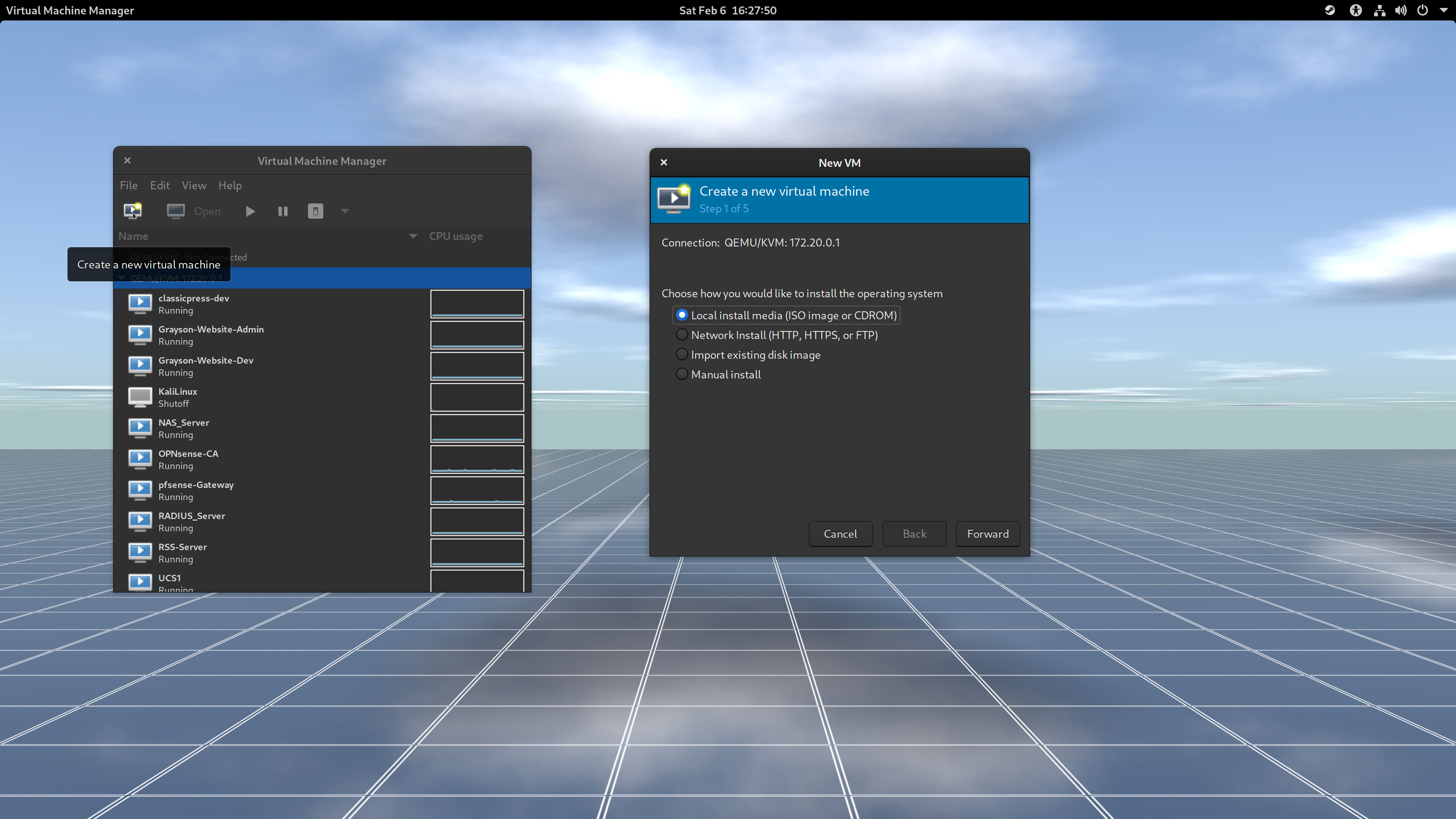
- With the remote server highlighted, click in the Create a new virtual machine button. A tooltip will come up if you hover over a monitor with a play button in the toolbar. (Figure 1-1)
- The Local install media is selected. Click Forward to go to the next screen. (Figure 1-1)
- To the right of Choose ISO or CDROM install media, click the Browse button to the right of the edit box. (Figure 1-2)
- In the list of storage pools, choose a pool that contains all hte ISOs you've downloaded. In my case, it's ISOs. (Figure 1-2)
- In the list of ISO files, look for
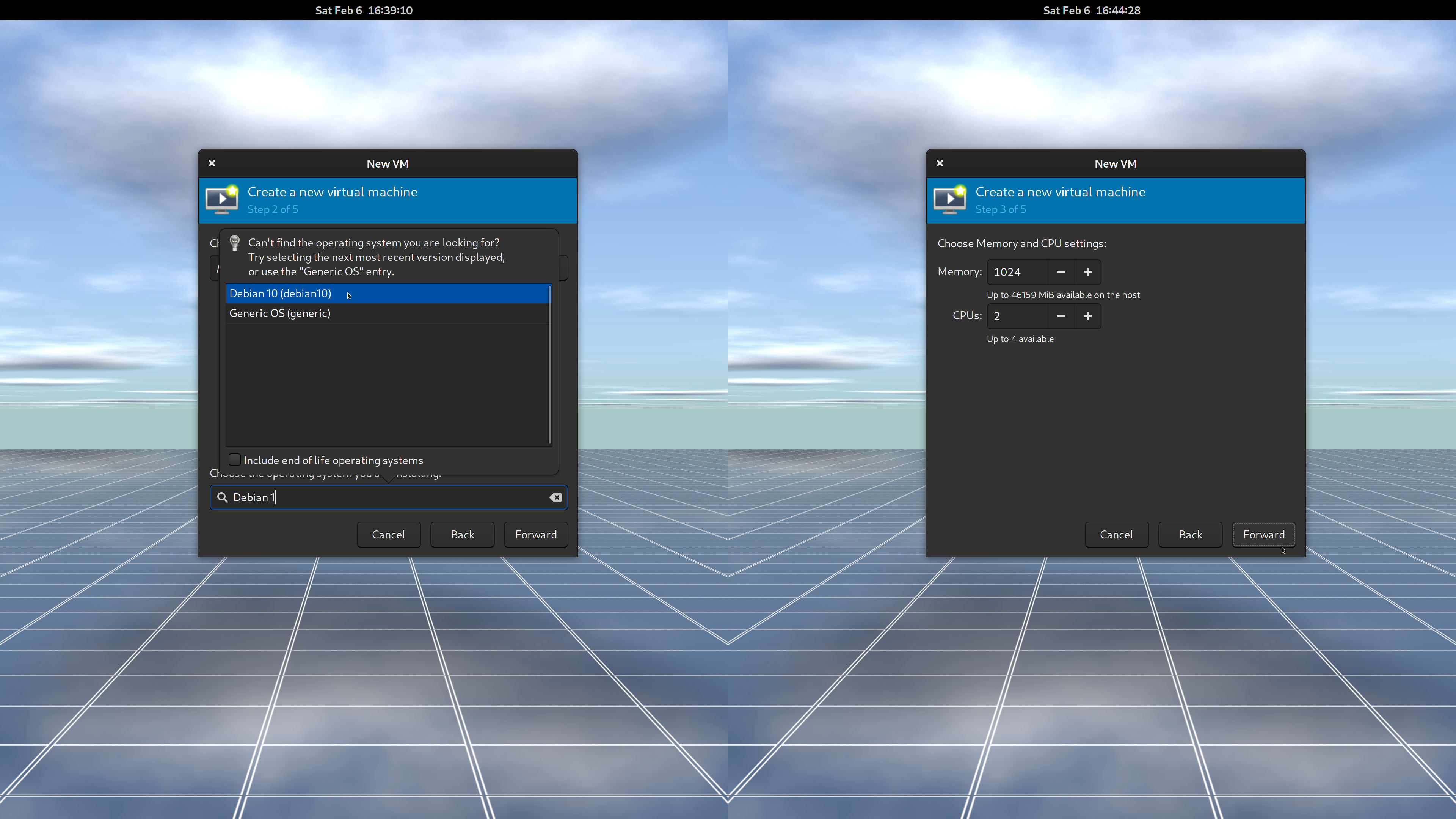
vyos-rolling-latest.iso. Then click Choose Volume to confirm your selection. (Figure 1-2) - In the Choose the operating system you are installing edit box, type
Debian 1and use the up and down arrow keys to select Debian 10. VyOS is based on Debian. Then click Forward. (Figure 1-3) - Accept the Memory and CPUs settings and click Forward. (Figure 1-3)
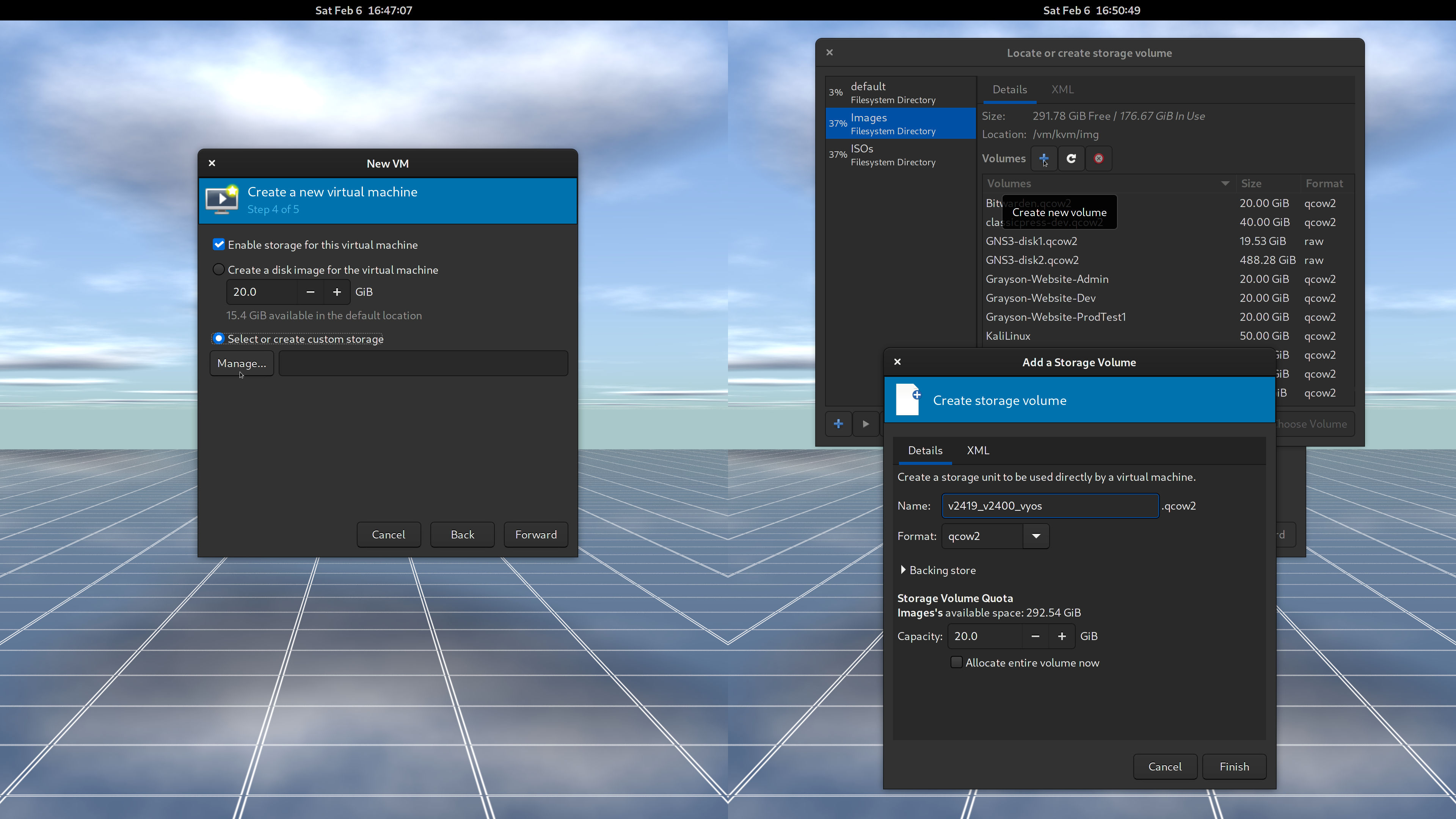
- Select or create custom storage and click Browse. (Figure 1-4)
- Select a storage pool where the disk images will be in (in my case, Images) and click the plus button next to Volumes to Create New Volume. Hover the mouse pointer over the plus sign for the tooltip to show up. (Figure 1-4)
Give the storage unit a name. Here is the convention and example name that I use. (Figure 1-4)
(VLAN ID for external network)_(VLAN ID for internal network)_(Operating System Name)
v2419_v2400_vyos
vstands for VLAN. VLAN 2419 will be the bridge that connects to pfSense (my edge router, a gateway to the Internet). VLAN ID 2400 is for an internal bridged network that VyOS VM will use.- Leave the rest as is and click Finish. Make sure you have plenty of disk space in your server! (Figure 1-4)
- Once you are back in the New VM, click the Forward button to continue to the last step for the wizard. (Figure 1-4)
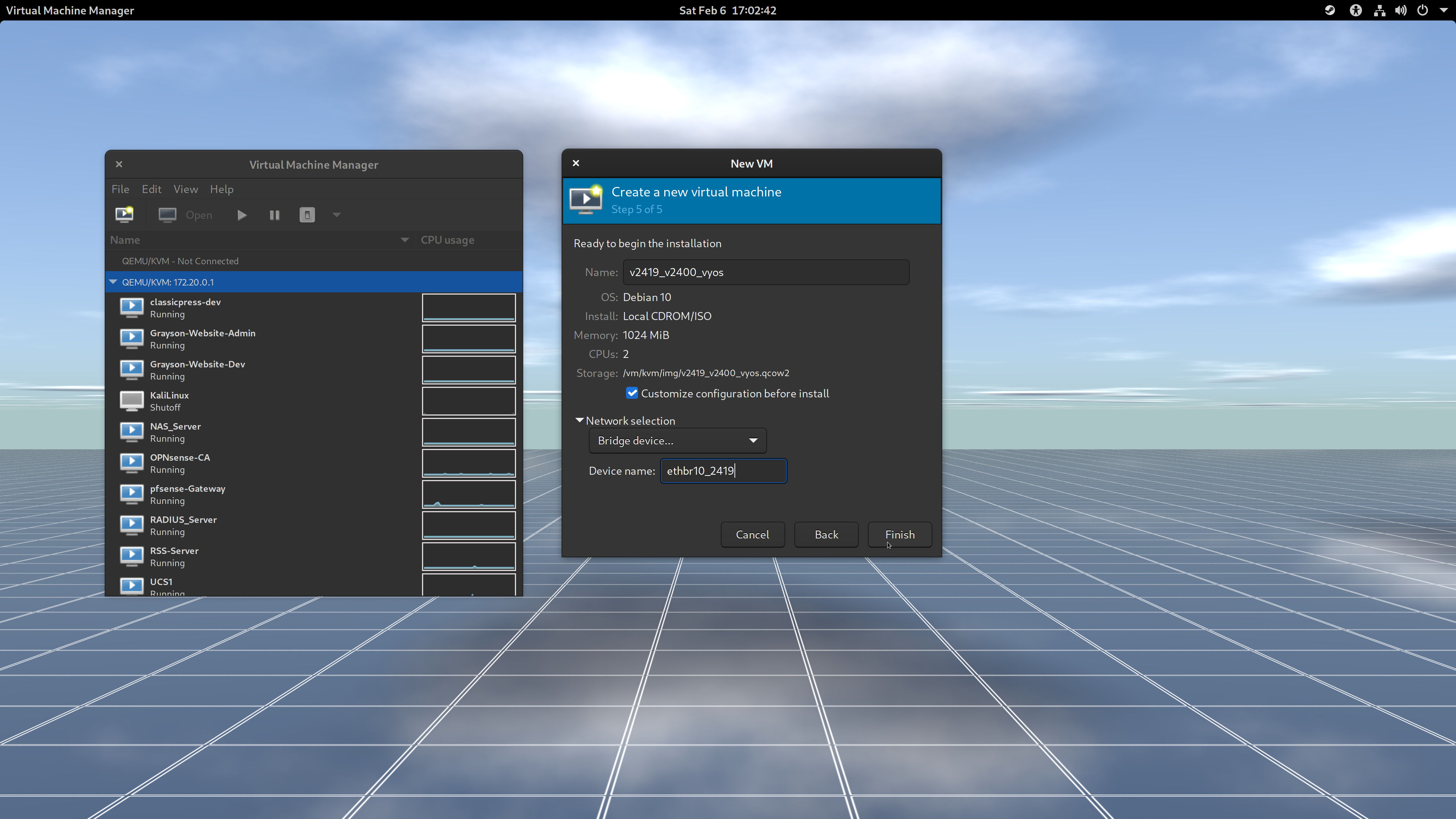
- Give your virtual machine the same Name as you created in Step 10. Keep the convention the same. (Figure 1-5)
- Check the checkbox for Customize the configuration before install. (Figure 1-5) A virtual machine will have two NICs (Network Interface Controllers).
Expand the Network selection, choose Bridge Device... from the dropdown menu, and in the Device name: edit box, assign the bridge to the first NIC. In my case, it's
ethbr10_2419. (Figure 1-5)Remember that VLAN 2419 is for the external network that connects to pfSense (
172.24.19.1). The VM will have an IP address of172.24.19.2/24. That will be for the central building of GalaxyTech. Read the scenario above if you need to.- Be sure you have Customize the configuration before install checked and click Finish. We're not done yet. (Figure 1-5)
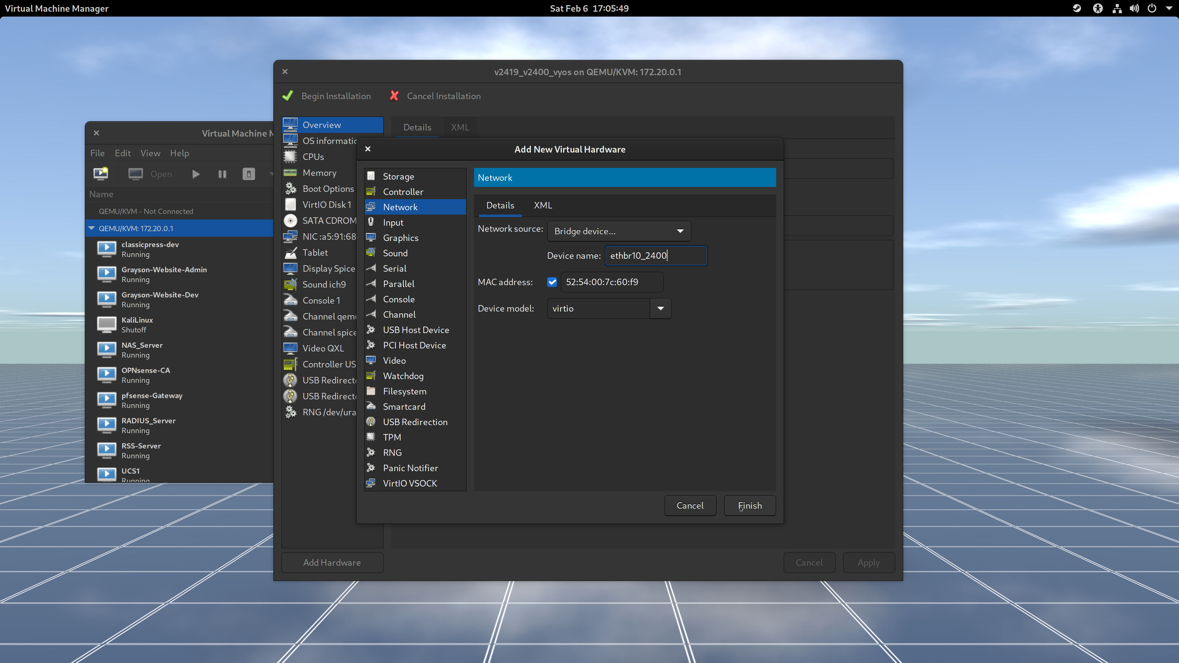
- Click in the Add Hardware at the bottom left-hand corner of the VM window. (Figure 1-6)
- In the list of hardware components, select Network. This is where a second NIC can be added. (Figure 1-6)
- Next to the Network source:, open the dropdown menu, choose Network bridge, and enter the name of the bridge in Device name. I chose a bridge for an internal network, which in my case it's
ethbr10_2400. 2400 is my VLAN ID. (Figure 1-6) When done, click Finish to return to the VM window. (Figure 1-6)
Notice that you have two NICs in the list of hardware components installed for the VM. (Figure 1-7)
- Now, it's time to Begin Installation. Click in that button in the upper-left corner and on we go!!!
(Return to Table of Content.)
Images for the installation of VyOS into the VM
vyos. Begin the installation of VyOS.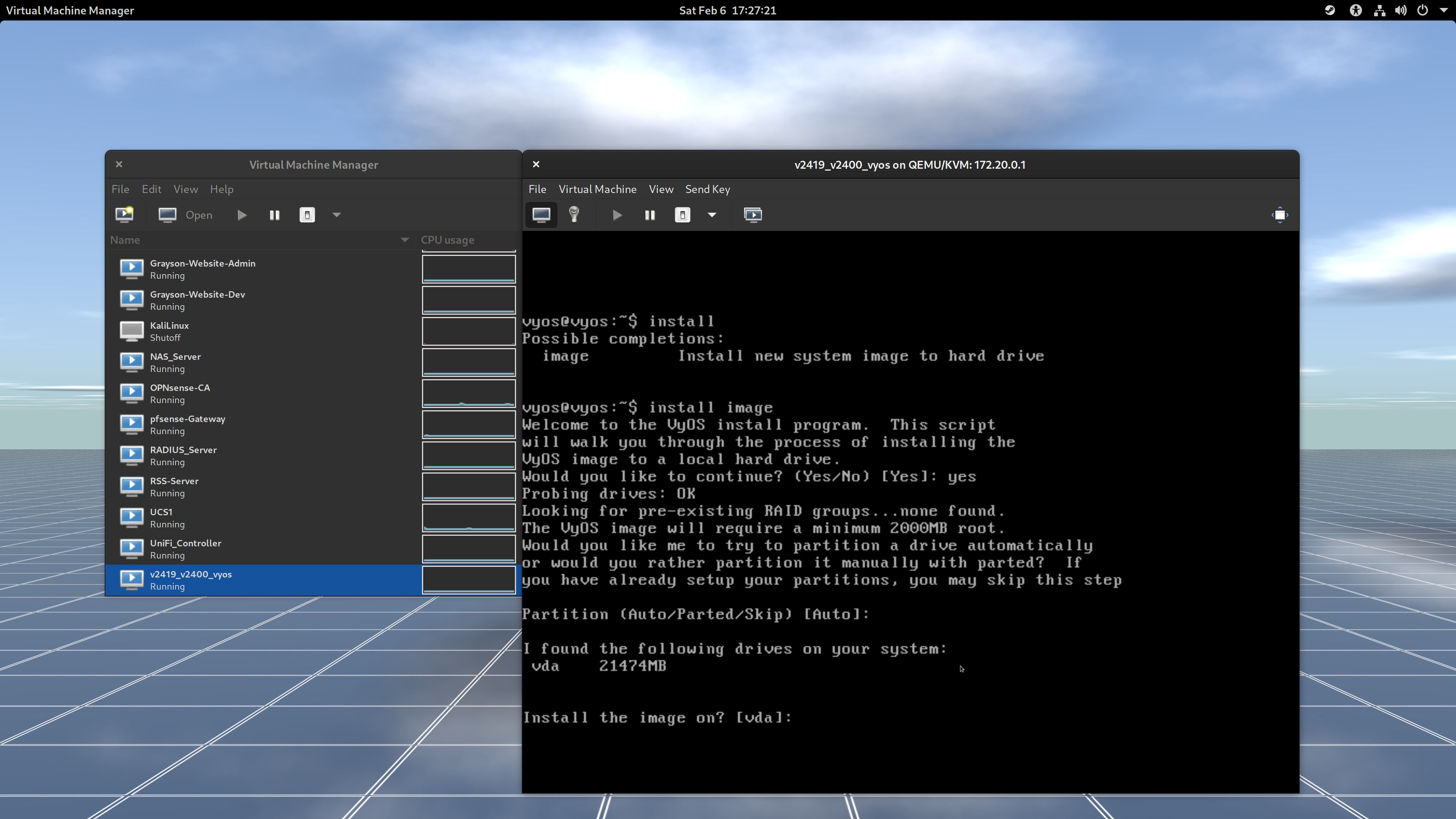
? to see the list of commands. Accept the defaults for partitioning the disk.
vyos.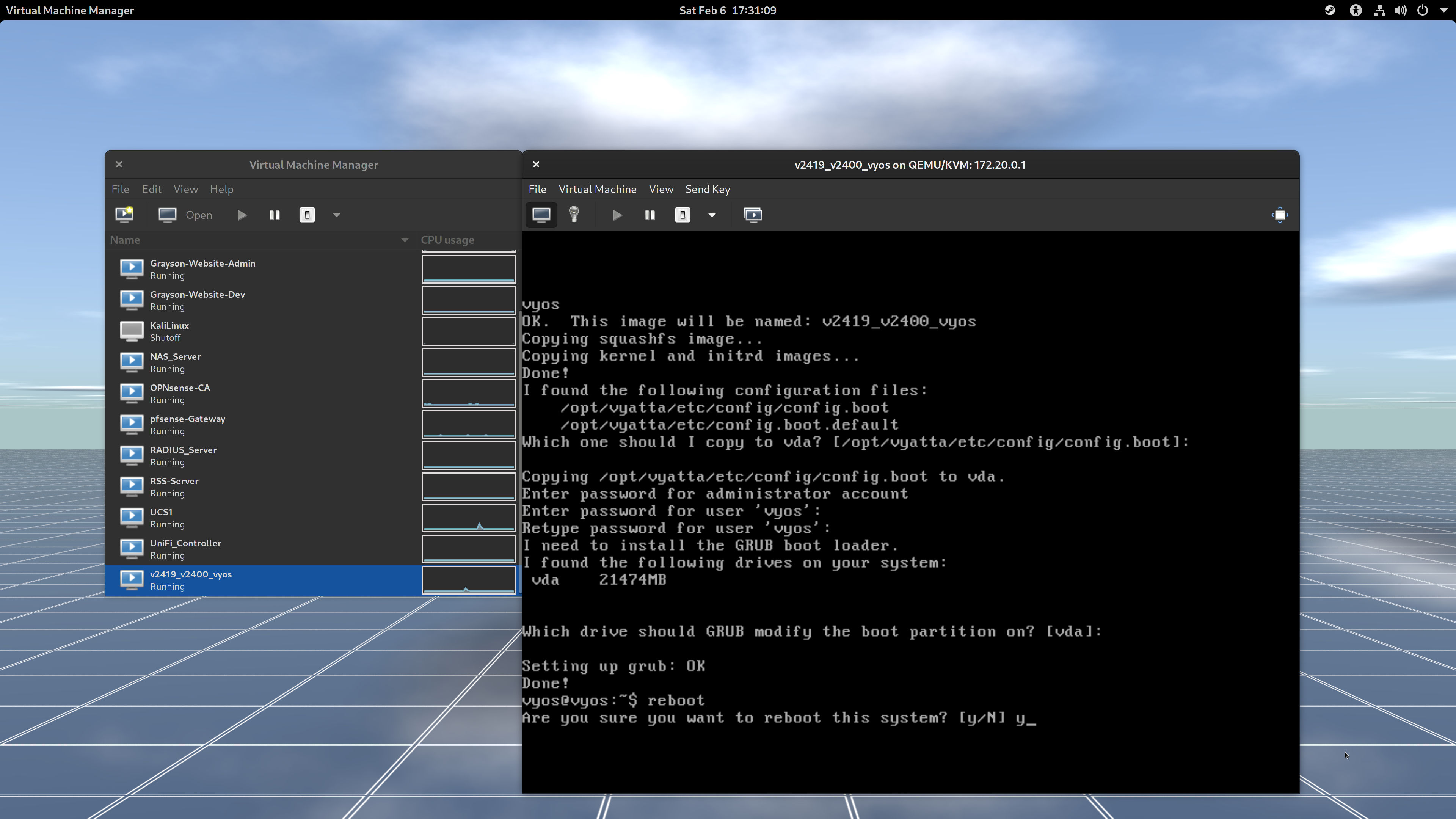
vda to install the bootloader into the disk. When done, reboot.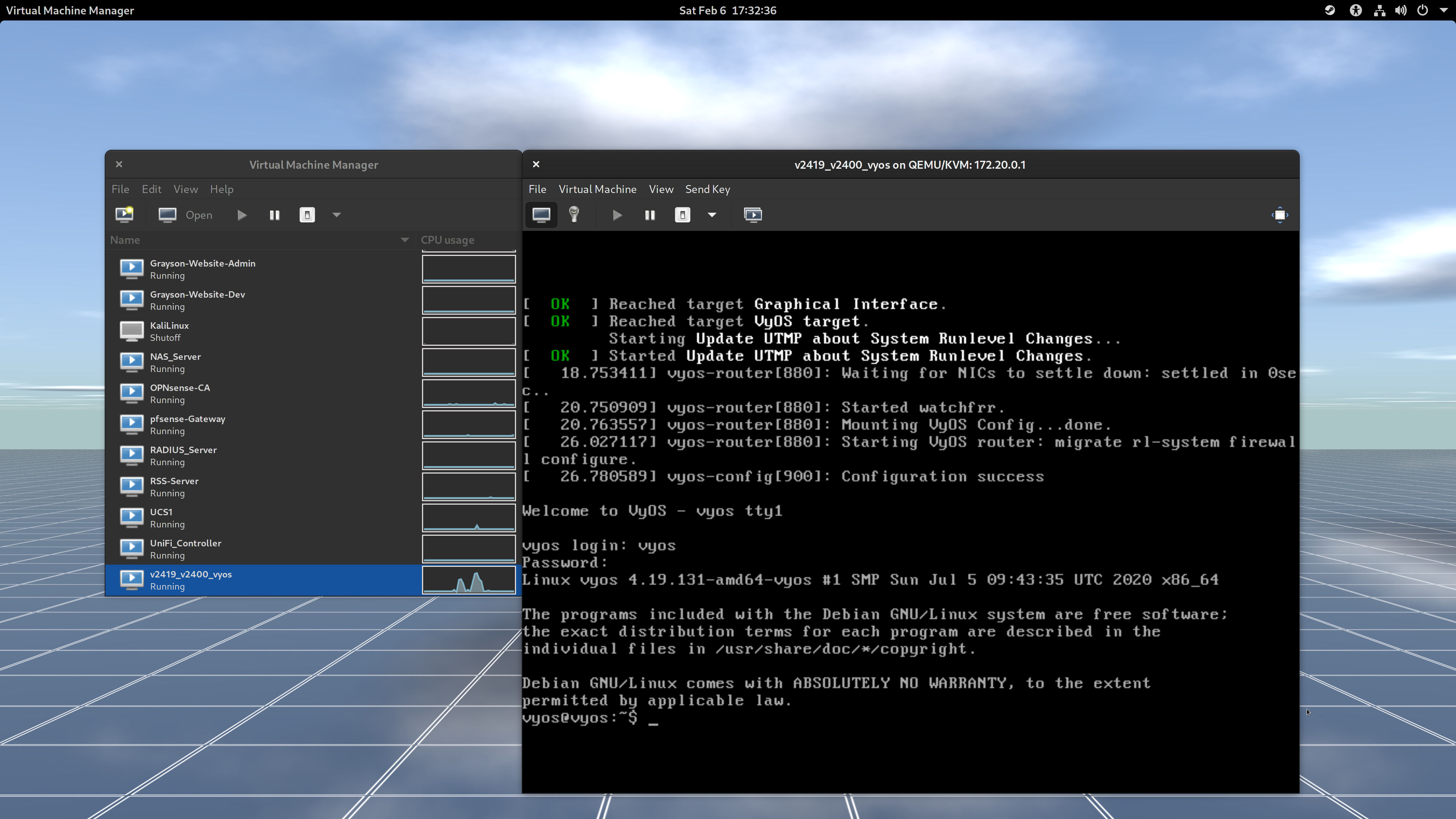
Install VyOS Into The First Instance of VM
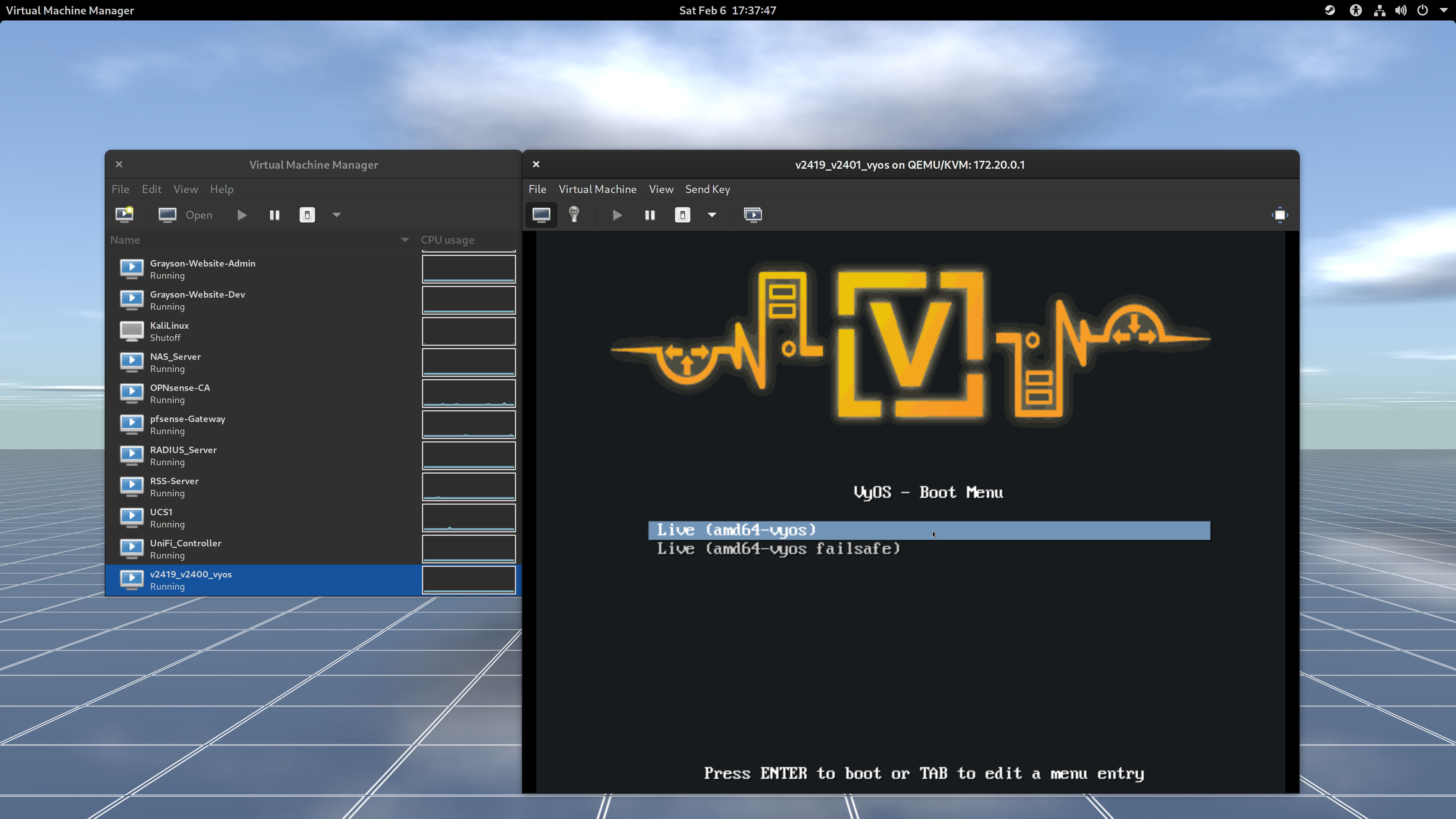
- When the bootloader shows up, leave the
Live (amd64-vyos)as selected and press Enter. (Figure 1-0) - When you get a login prompt, the username and password is
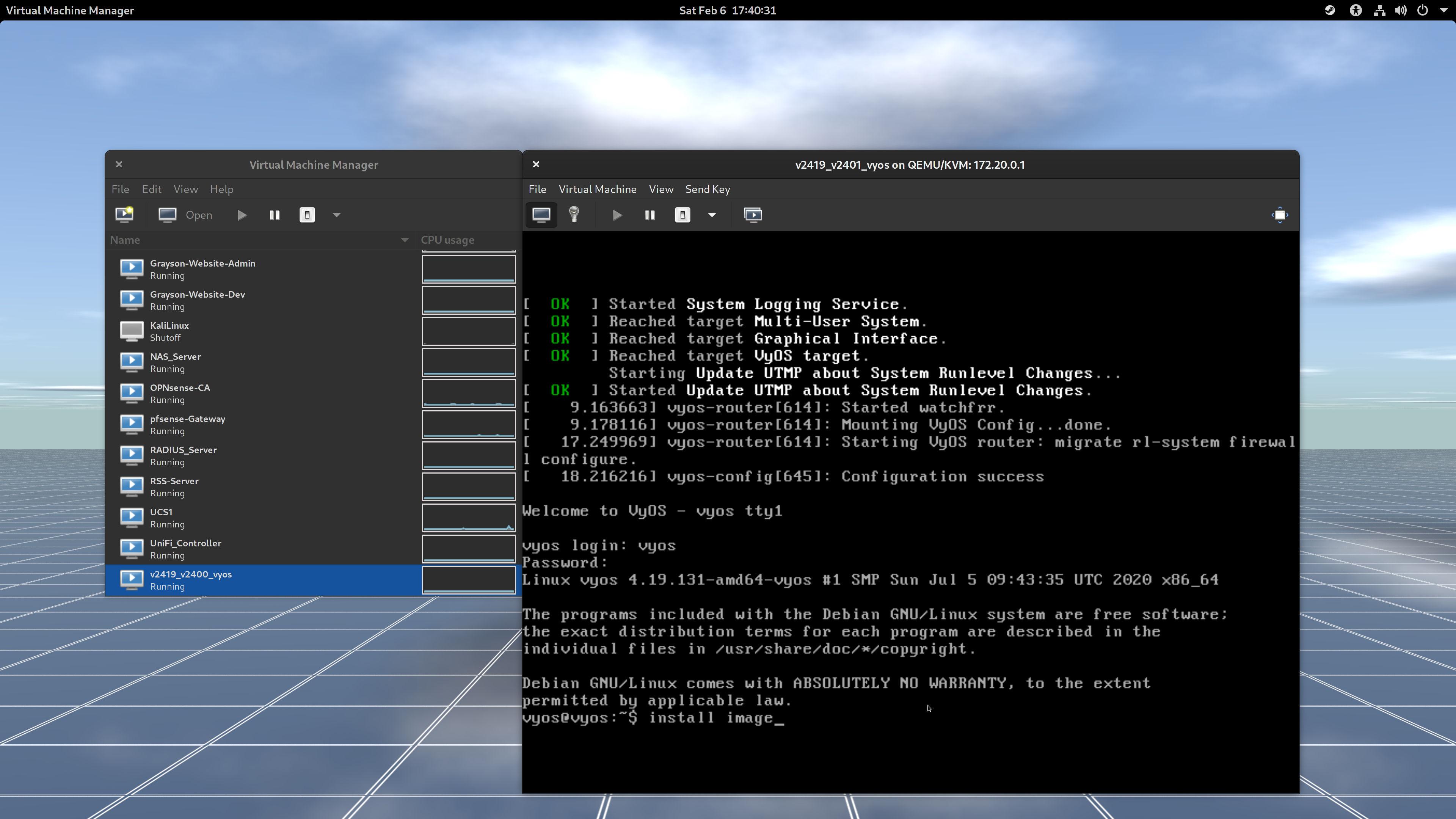
vyos. (Figure 1-1) Type the following command to begin the installation of VyOS. (Figure 1-1 and 1-2)
install image
Then press Enter. Note that you can type
?to see the list of commands and parameters. (Figure 1-2)- The installer has found a disk to partition in callsed
vda. Go ahead and accept the defaults (autoandvda). (Figure 1-2) - Input
Yesto continue the installation as the disk is empty. (Figure 1-3) - You can leave everything as default until you get to create a password. Note that I should have left the image name as-is. An image is an image similar to Cisco IOS; however, I did enter
v2419_v2400_vyos. Just leave the image name as default. (Figure 1-3) - Enter the password that you can easily remember. (Figure 1-3)
- Once you are done creating a password, leave the rest as defaults and reboot. (Figure 1-4)
- Once rebooted, login with the user
vyosalong with your newly-created password and you're in!
Congratulations! You've just created yourself a first virtual machine and installed VyOS! Before you continue configuring the network, let's create another virtual machine and install VyOS.
(Return to Table of Content.)
Create a Second VM and Install VyOS
I have already provided instructions for creating a virtual machine and installing VyOS into the VM. In Step 10 and Step 13, give your new disk and VM the new name while still following the convention.
(VLAN ID for external network)_(VLAN ID for internal network)_(Operating System Name)
v2419_v2401_vyos
Your VM will use a different internal bridge name for the second VLAN, which has an ID of 2401. So, in Step 19 (third from the last step), you would enter ethbr10_2401 for the second NIC. So, here's how I have it setup:
| VM Name | External NIC | Internal NIC |
|---|---|---|
v2419_v2400_vyos |
ethbr10_2419 |
ethbr10_2400 |
v2419_v2401_vyos |
ethbr10_2419 |
ethbr10_2401 |
v2419_v2402_pfSense |
ethbr10_2419 |
ethbr10_2402 |
And the IP addresses and subnet prefixes are going to be:
| VM Name | Public IP | Private IP |
|---|---|---|
v2419_v2400_vyos |
172.24.19.2/24 |
10.249.0.1/24 |
v2419_v2401_vyos |
172.24.19.3/24 |
10.249.1.1/24 |
v2419_v2402_pfSense |
172.24.19.4/24 |
10.249.2.1/24 |
Note that I simply wanted to pretend that anything in 172.24.19.x/24 is part of the public IP addressing scheme. 172.24.19.x/24 is still part of 172.16.x.x/12 private subnet (RFC 1918). Only for this article, I'm going to pretend that anything in 172.24.19.x/24 will have a public IP address assigned to each of the three virtual machines. A fake one, if you will.
(Return to Table of Content.)
Images for the installation of pfSense into the third VM

1.1.1.1 to confirm the Internet is working.Create a Third VM and Install pfSense In a VM
I am very sure you can create a new VM named v2419_v2402_pfSense with an internal network bridge named ethbr10_2402. If not, look over the steps on how to create a new VM. Be sure to keep ethbr10_2419 as the device name for the first NIC in the New VM dialog.
Now the steps for installing and configuring pfSense is as follows:
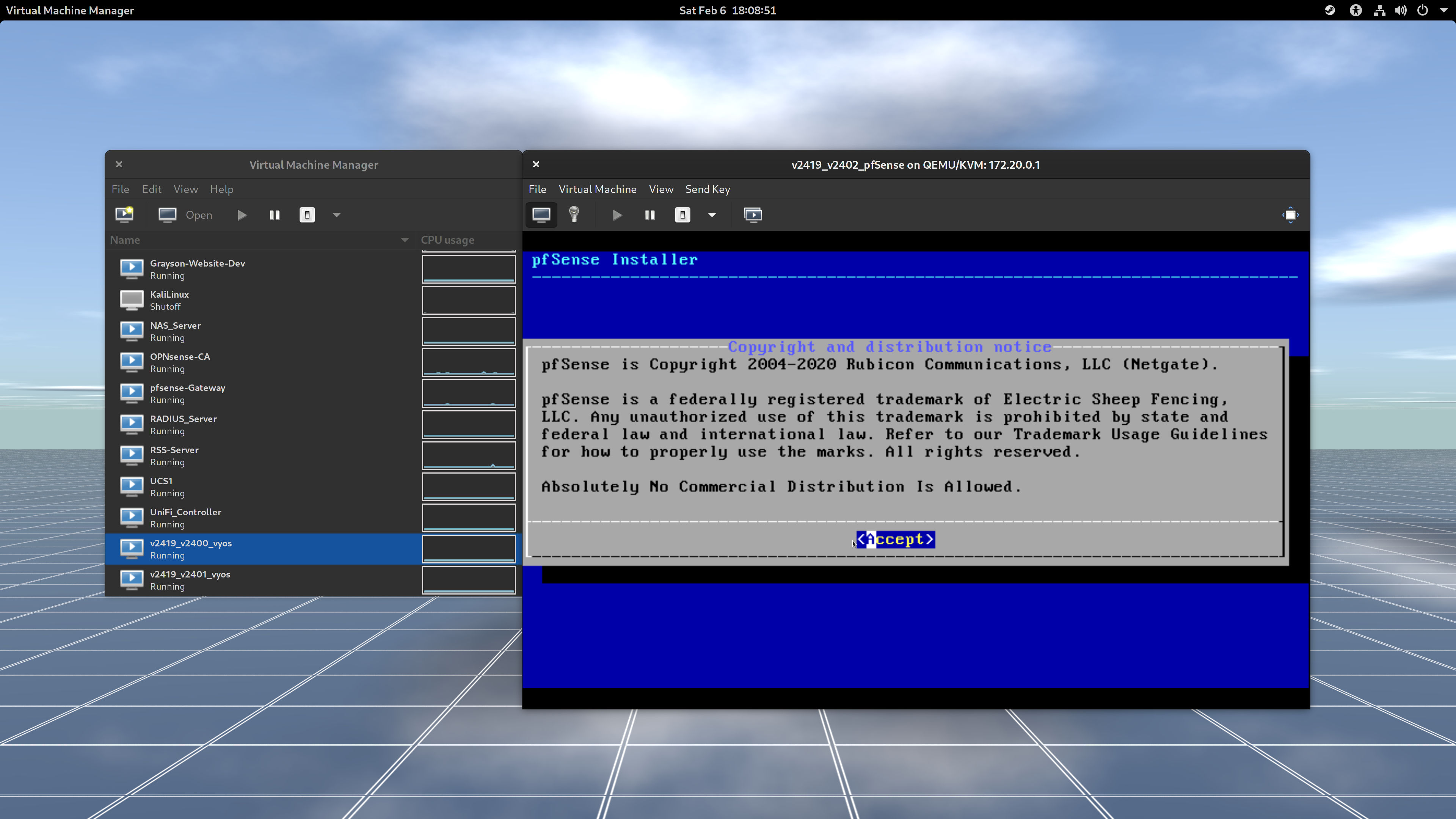
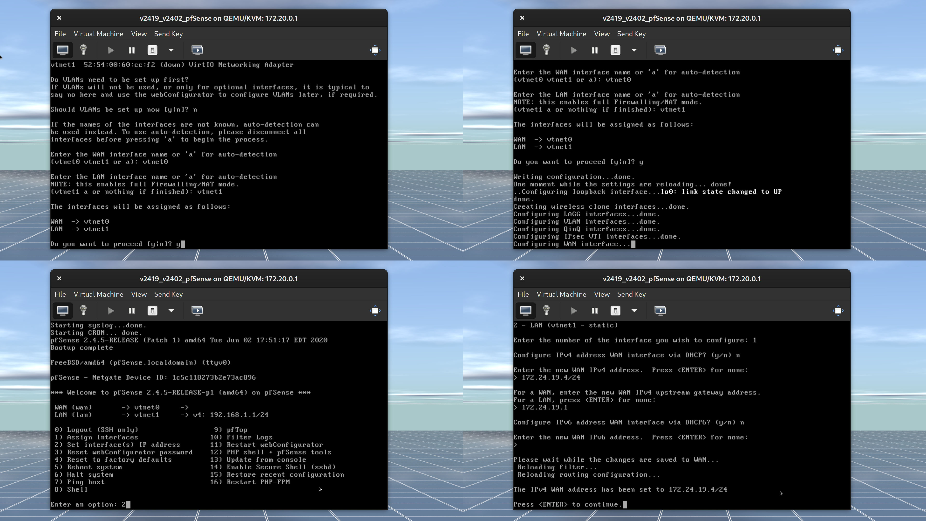
- Go ahead and press the Enter key throughout the installation process. The installer will insteall pfSense into the virtual disk and prompt you to reboot the system. (Figure 1-1 and 1-2)
Set vtnet0 as WAN and vtnet1 as LAN. (Figure 1-3)
pfSense will attempt to discover an IP address if a DHCP server is configured. If not, wait for pfSense to time out. (Figure 1-3)
- When you get to the menu, type to select
2and press Enter. (Figure 1-3) - Enter
1forvtnet0. Typenas DHCP server was not configured. (Figure 1-3) - Enter the IP address for external network. In my case, it's
172.24.19.4/24. If I omit/24from the IP address, I will be asked to input a subnet bit (or a prefix number).24is what I would enter. (Figure 1-3) - If you have no need for IPv6, simply type
n, hit Enter, and hit Enter again to leave the next line blank. - Now here's something I screwed up on. Not shown in Figure 1-3 is it asks if you want to revert back to HTTP instead of keeping in HTTPS. Idealy, for a production environment you always want HTTPS for protection against on-path attacks, which is also known as man-in-the-middle (MiTM) attack. Because this is a homelab and I have kept the networks segregated from each other, HTTP is fine.
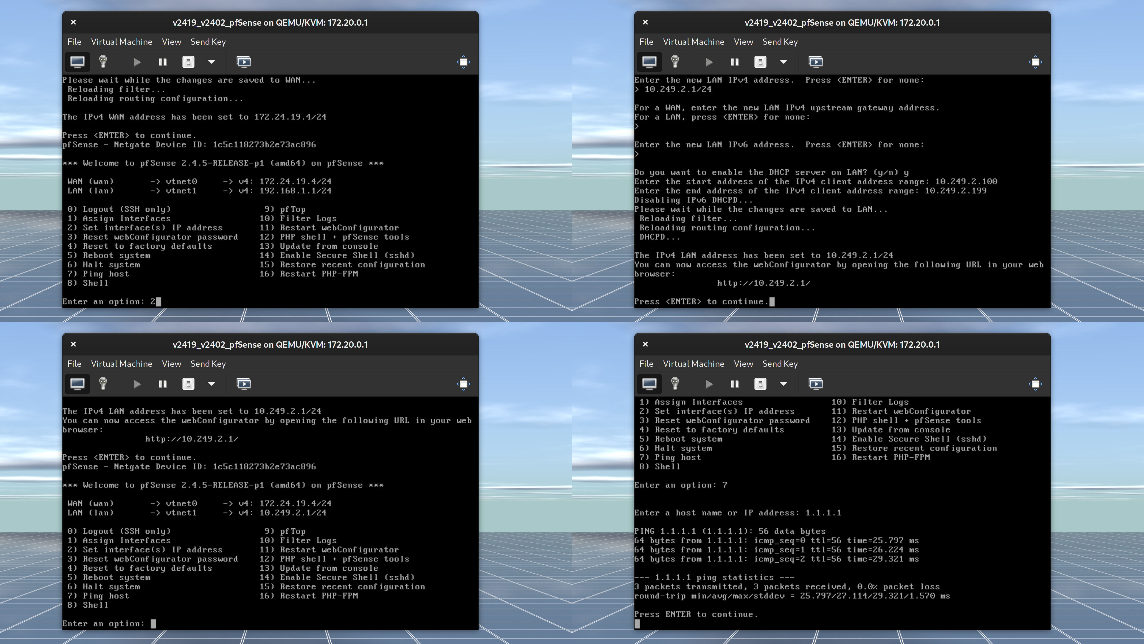
- Press the Enter key and you should be back on the menu. (Figure 1-4)
- Press
2again and press Enter to get into the interface configuration. You'll want to configure the LAN address which is number2. - If you only want IPv4, simply enter the IP address and subnet mask (in my case,
10.249.2.1/24) and leave the rest set to default. Press Enter at the last step to get back to the menu. - To make sure everything is working, press
7, hit Enter, and ping (don't typeping) 1.1.1.1. If it's working, you are good to go.
Congratulations on installing and setting up pfSense. But it's not over yet. You will need to setup another virtual machine to configure pfSense. But let's get the network up and running in two VyOS instances first.
(Return to Table of Content.)
Configure the First Instance of VyOS
If you are familiar with Cisco's IOS, then the commands will be a lot different. First, and foremost, there's no such thing as privileged EXEC mode. The $ sign means you are in user mode. If you type sudo -i or configure, VyOS will put you in "#" mode. Please note the following output below:
vyos@vyos:~$ sudo -i
root@vyos:~# exit
logout
vyos@vyos:~$ configure
[edit]
vyos@vyos# hostname v2400-vyos
hostname: you must be root to change the hostname
[edit]
vyos@vyos# set hostn?
  Configuration path: [hostn] is not valid.
[edit]
vyos@vyos#
VyOS is a full Linux distribution. Every VyOS command begins with "set" once you are in VyOS configuration mode. Even though VyOS is a Linux distribution that is focused in routing, please do not edit the /etc/hostname file as root. Instead, perform the following commands:
vyos@vyos:~$ configure
[edit]
vyos@vyos# set system host-name v2400-vyos
[edit]
vyos@vyos# commit
[edit]
vyos@vyos# save
Saving configuration to '/config/config.boot'...
[edit]
vyos@vyos# exit
exit
vyos@vyos:~$ reboot
Are you sure you want to reboot this system? [y/N] y
Reboot the system and you should be back in VyOS with a new hostname. Set the hostname for the second VyOS instance (different VM) to v2401-vyos and reboot the VM. The commit command commits changes to memory and save saves changes to the disk as /config/config.boot. VyOS will complain that changes made to /etc/hostname and then executing the two set commands above will cause VyOS to error out saying "temporary failure in name resolution" or something like that. So yea, unlike Cisco IOS's hostname v2400-cisco in global configuration mode, changes in VyOS do not take effect even once the changes have been commited to memory and saved to disk. However, just about all the networking commands you'll be doing will take effect once you call commit in configuration mode.
See what happens if you configure a domain name for your VyOS router. You can name whatever domain name you want. I suggest you keep the TLD set to lan so you won't cause confusion with a .com domain.
configure
set system domain-name lab.graysonpeddie.lan
commit
discard
save
set system domain-name lab2.graysonpeddie.lan
discard
The first command gets you into configuration mode. I then configure the domain name for the router. I commited the changes to memory but decided to discard the changes. Because the change has been stored in RAM, I get an error message saying No changes have been discarded. Then, I changed the domain name to lab2.graysonpeddie.lan but decided to discard the changes. So even if I make changes to network configuration, the changes won't take effect until I commit to RAM and then save changes to disk.
Now, let's get into networking, shall we? First, we must configure the interfaces for v2419-v2400-vyos. Make sure you are in configuration mode. There should be no :~ between hostname and number sign. Remember, sudo -i takes you into root mode just like all other Linux distributions do.
set interfaces ethernet eth0 address 172.24.19.2/24
set interfaces ethernet eth1 address 10.249.0.1/24
set protocols static route 0.0.0.0/0 next-hop 172.24.19.1
commit
save
And for v2419-v2401-vyos VM:
set interfaces ethernet eth0 address 172.24.19.3/24
set interfaces ethernet eth1 address 10.249.1.1/24
set protocols static route 0.0.0.0/0 next-hop 172.24.19.1
commit
save
Once you exit the configuration mode for both of them, can you ping 1.1.1.1 in both VMs? If yes, you are in good shape! 0.0.0.0/0 means a default gateway of last resort. 1.1.1.1 is not in the routing table, so the router has to go through 172.24.19.1 in order to reach out to 192.168.1.254, which is my mom's router, and 192.168.2.254, which is the Comtrend router for Consolidated Communications. Because I do not have a way of getting traceroute information from a virtual machine, I can do that from my desktop PC. Note that I cannot ping 172.20.0.2, which is the edge router for pfSense that reaches out to the Internet. I don't want my internal hosts to ping my edge gateway for security and obscurity reasons.
[grayson@grayson-epcotcenter Storage]$ traceroute 1.1.1.1
traceroute to 1.1.1.1 (1.1.1.1), 30 hops max, 60 byte packets
 1  _gateway (172.20.1.1)  0.191 ms  0.143 ms  0.136 ms
 2  * * *
 3  192.168.2.254 (192.168.2.254)  4.231 ms  4.246 ms  4.267 ms
 4  sdsl-blt-216-227-16-10.gtcom.net (216.227.16.10)  14.952 ms  14.960 ms  14.976 ms
 5  rblt-aa.gtcom.net (216.227.16.1)  15.049 ms  15.080 ms  15.023 ms
 6  atl-b22-link.telia.net (62.115.9.130)  24.028 ms atl-b22-link.telia.net (80.239.192.68)  23.200 ms  23.194 ms
 7  cloudflare-ic-309901-atl-bb1.ip.twelve99-cust.net (213.248.83.18)  53.332 ms cloudflare-ic-301665-atl-bb1.c.telia.net (62.115.32.222)  43.354 ms  43.360 ms
 8  one.one.one.one (1.1.1.1)  32.600 ms  24.107 ms  21.845 ms
[grayson@grayson-epcotcenter Storage]$ ping 172.20.0.2
PING 172.20.0.2 (172.20.0.2) 56(84) bytes of data.
^C
--- 172.20.0.2 ping statistics ---
4 packets transmitted, 0 received, 100% packet loss, time 3055ms
[grayson@grayson-epcotcenter Storage]$
(Return to Table of Content.)
DHCP
For learning experience, let's configure DHCP server for both VyOS routers. I'm going to start with v2419-v2400-vyos VM in configuration mode.
edit service dhcp-server shared-network-name InternalNetwork2400 subnet 10.249.0.0/24
set range P1 start 10.249.0.100
set range P1 stop 10.249.0.199
set default-router 10.249.0.1
set name-server 1.1.1.1
commit
save
Here's another way without the use of edit:
set service dhcp-server shared-network-name InternalNetwork2400 subnet 10.249.0.0/24 range P1 start 10.249.0.100
set service dhcp-server shared-network-name InternalNetwork2400 subnet 10.249.0.0/24 range P1 stop 10.249.0.199
set service dhcp-server shared-network-name InternalNetwork2400 subnet 10.249.0.0/24 default-router 10.249.0.1
set service dhcp-server shared-network-name InternalNetwork2400 subnet 10.249.0.0/24 name-server 1.1.1.1
commit
save
I'll let you figure out why I use the edit command as a shortcut.
And for v2419-v2401-vyos VM in configuration mode:
edit service dhcp-server shared-network-name InternalNetwork2401 subnet 10.249.1.0/24
set range P1 start 10.249.1.100
set range P1 stop 10.249.1.199
set default-router 10.249.1.1
set name-server 1.1.1.1
commit
save
P1 is just a text field for the range. Think of it as a pool of IP addresses. This allows VMs to acquire an IP address from the router that connects to it.
NAT
Endpoint devices using private IP addresses need to communicate over the Internet over a public IP address. Configure NAT in both VyOS virtual machines. Remember, this can only be done in configuration mode.
set nat source rule 1 translation address masquerade
set nat source rule 1 outbound-interface eth0
commit
save
Setting a translation address to masquerade allows endpoint devices to act as though it has its own public IP address.
(Return to Table of Content.)
OSPF
Now this is where OSPF comes into play. But first, I will create two virtual machines--one of which connect to their own network behind VyOS routers. In order to do that, though, I will have to set up my virtual machine environment in my desktop machine.
[grayson@grayson-epcotcenter ~]$ sudo usermod -a -G libvirt grayson
[sudo] password for grayson:
[grayson@grayson-epcotcenter ~]$ sudo systemctl enable libvirtd
Created symlink /etc/systemd/system/multi-user.target.wants/libvirtd.service → /usr/lib/systemd/system/libvirtd.service.
Created symlink /etc/systemd/system/sockets.target.wants/virtlockd.socket → /usr/lib/systemd/system/virtlockd.socket.
Created symlink /etc/systemd/system/sockets.target.wants/virtlogd.socket → /usr/lib/systemd/system/virtlogd.socket.
Created symlink /etc/systemd/system/sockets.target.wants/libvirtd.socket → /usr/lib/systemd/system/libvirtd.socket.
Created symlink /etc/systemd/system/sockets.target.wants/libvirtd-ro.socket → /usr/lib/systemd/system/libvirtd-ro.socket.
For changes to take into effect, I have to log out and back in for the libvirt group to take effect for my user grayson. But instead of logging out and back in, I'm going to restart my machine. I could even execute a start command for libvirtd if I want. libvirtd daemon (similar to a "service" in Windows) is what allows me to run virtual machines in my desktop without root privileges.
Once I restart my desktop machine, I am able to spin up 3 virtual machines, install Pop!_OS, and ping the router's IP addresses. My desktop had 32GB of RAM and my server has 48GB of RAM. For my desktop, I can give the three virtual machines each having 4GB of RAM. Of course, I cannot ping each other's internal endpoints because each router (be it VyOS or pfSense) does not know how to reach their own network that came from a different router.
While we can set static routes for each VyOS router as we did for setting a default gateway, we are going to make use of OSPF. More information about OSPF can be found in this web page. Actually, the web page I linked can show you how to configure Cisco routers using OSPF, but I am only focusing in VyOS and pfSense for now.
Let's learn how we can configure OSPF in two of the VyOS instances. Let's start with v2419-v2400-vyos and then configure v2419-v2401-vyos.
vyos@v2400-vyos# edit protocols ospf
vyos@v2400-vyos# area 0 network 10.249.0.0/24
vyos@v2400-vyos# area 0 network 172.24.19.0/28
vyos@v2400-vyos# parameters router-id 10.249.0.1
vyos@v2400-vyos# commit
vyos@v2400-vyos# save
vyos@v2401-vyos# edit protocols ospf
vyos@v2401-vyos# area 0 network 10.249.1.0/24
vyos@v2401-vyos# area 0 network 172.24.19.0/28
vyos@v2401-vyos# parameters router-id 10.249.1.1
vyos@v2401-vyos# commit
vyos@v2401-vyos# save
Each router has two networks in the same area and the router ID is the neighbor ID. Let's exit the configuration mode and have a look at the neighbors.
vyos@v2400-vyos# exit
exit
vyos@v2400-vyos:~$ sh ip ospf neighbor
Neighbor ID     Pri State           Dead Time Address         Interface                        RXmtL RqstL DBsmL
10.249.1.1        1 Full/Backup       37.035s 172.24.19.3     eth0:172.24.19.2                     0     0     0
vyos@v2401-vyos# exit
exit
vyos@v2401-vyos:~$ sh ip ospf neigh
Neighbor ID     Pri State           Dead Time Address         Interface                        RXmtL RqstL DBsmL
10.249.0.1        1 Full/DR           33.747s 172.24.19.2     eth0:172.24.19.3                     0     0     0
Pay no attention to the last three columns including the dead time (actually, you can read more about dead time that I linked here). The two VyOS routers can see each other. Each router has an outbound interface which is eth0 and has its IP address assigned. From 10.249.0.0/24, to get to 10.249.1.0/24, the router goes out from 172.24.19.2 to 172.24.19.3 in order to reach the 10.249.1.0/24 subnet. So, from my virtual machine running Pop!_OS that connects to v2400-vyos, my VM's IP address is 10.249.0.100 and when I ping 10.249.1.100 the ping is successful.
I then ping from another virtual machine that is connected to v2401-vyos VM. Its IP address is 10.249.1.100. I ping 10.249.0.100 and if you look at the neighbor for v2401-vyos, the ping is successful.
So everything is successful between two VyOS instances, right? Let's configure the firewall next.Update as of October 24, 2021
Oh, and here is something I forgot to mention. It's about setting passive interfaces. None of the hosts inside the private network should know anything about OSPF traffic. That's where the next command comes in.
set protocols ospf passive-interface eth1
That way, VyOS will not broadcast OSPF into the internal network. What if you have 5 networks? Let's say there are 4 LAN networks and 1 network that connects to other OSPF-enabled routers such as pfSense and Cisco ISR routers. You can use the set of commands instead as shown below.
set protocols ospf passive-interface default
set protocols ospf passive-interface-excluse eth0
All the interfaces are set to passive by default except the one that connects to the OSPF network and out to the Internet.
(Return to Table of Content.)
Firewall
Why is firewall important? It's to keep the bad guys out and control which traffic can go in and out. Let's configure the firewall for both VyOS VMs.
First, I will show you the configuration.
vyos@v2400-vyos# show firewall
 name WANIn {
     default-action drop
     rule 1 {
         action accept
         state {
             established enable
             related enable
         }
     }
     rule 2 {
         action accept
         source {
             address 172.24.19.0/28
         }
     }
     rule 3 {
         action accept
         source {
             address 10.249.0.0/16
         }
     }
 }
 name WANLocal {
     default-action accept
     rule 1 {
         action accept
         state {
             established enable
             related enable
         }
     }
     rule 2 {
         action accept
         protocol ospf
     }
 }
[edit]
vyos@v2400-vyos#
vyos@v2401-vyos# sh firewall
 name WANIn {
     default-action drop
     rule 1 {
         action accept
         state {
             established enable
             related enable
         }
     }
     rule 2 {
         action accept
         source {
             address 172.24.19.0/28
         }
     }
     rule 3 {
         action accept
         source {
             address 10.249.0.0/16
         }
     }
 }
 name WANLocal {
     default-action drop
     rule 1 {
         action accept
         state {
             established enable
             related enable
         }
     }
     rule 2 {
         action accept
         protocol ospf
     }
-    rule 3 {
-        action accept
-        destination {
-            port 22
-        }
-        protocol tcp
-    }
 }
[edit]
vyos@v2401-vyos#
I will start with the commands for v2400-vyos and you can go from there.
edit firewall name WANIn
default action drop
...
But before you enter the commands above and figure out the rest, let me ask you this. What does a dash indicate?
If you guess "the changes will be deleted before it's commited to RAM," you are correct. This is how to delete the firewall rule:
delete firewall name WANLocal rule 2
Now go ahead and perform the rest of the commands. Follow the hierarchy!
Did you complete all the commands? Okay! More questions for you! How do you assign the two sets of firewall chains to the outbound interface?
Do you know how you configured IP addresses for your interfaces? Use the ? and TAB key to help you out.
set interfaces ethernet eth0 firewall in name WANIn
set interfaces ethernet eth0 firewall local WANLocal
What does WANIn and WANLocal do?
The firewall controls the flow of traffic coming into the router (WANLocal) or into the network (WANIn). However, the firewall chain for out has not been configured. This is fine for what we need to setup OSPF.
Can you ping each other's public IP addresses (172.24.19.x)? If no, what do you need to do in order to allow the public IP addresses to ping each other? I'll give you a hint...
Allow ICMP in the local chain.
(Return to Table of Content.)
Are We Done with VyOS?
How did we do so far? Let's list the configurations for both of the VyOS routers:
vyos@v2400-vyos:~$ sh conf
firewall {
    all-ping enable
    broadcast-ping disable
    config-trap disable
    ipv6-receive-redirects disable
    ipv6-src-route disable
    ip-src-route disable
    log-martians enable
    name WANIn {
        default-action drop
        rule 1 {
            action accept
            state {
                established enable
                related enable
            }
        }
        rule 2 {
            action accept
            source {
                address 172.24.19.0/28
            }
        }
    }
    name WANLocal {
        default-action accept
        rule 1 {
            action accept
            state {
                established enable
                related enable
            }
        }
        rule 2 {
            action accept
            protocol ospf
        }
    }
    receive-redirects disable
    send-redirects enable
    source-validation disable
    syn-cookies enable
    twa-hazards-protection disable
}
interfaces {
    ethernet eth0 {
        address 172.24.19.2/24
        firewall {
            in {
                name WANIn
            }
            local {
                name WANLocal
            }
        }
        hw-id 52:54:00:a5:91:68
    }
    ethernet eth1 {
        address 10.249.0.1/24
        hw-id 52:54:00:7c:60:f9
    }
    loopback lo {
    }
}
nat {
    source {
        rule 1 {
            outbound-interface eth0
            translation {
                address masquerade
            }
        }
    }
}
protocols {
    ospf {
        area 0 {
            network 10.249.0.0/24
            network 172.24.19.0/28
        }
        parameters {
            abr-type cisco
            router-id 10.249.0.1
        }
    }
    static {
        route 0.0.0.0/0 {
            next-hop 172.24.19.1 {
            }
        }
    }
}
service {
    dhcp-server {
        shared-network-name InternalNetwork2400 {
            subnet 10.249.0.0/24 {
                default-router 10.249.0.1
                name-server 1.1.1.1
                range P1 {
                    start 10.249.0.100
                    stop 10.249.0.199
                }
            }
        }
    }
    ssh {
        listen-address 10.249.0.1
    }
}
system {
    config-management {
        commit-revisions 100
    }
    console {
        device ttyS0 {
            speed 115200
        }
    }
    domain-name lab1.graysonpeddie.lan
    host-name v2400-vyos
    login {
        user vyos {
            authentication {
                encrypted-password ****************
                plaintext-password ****************
            }
        }
    }
    name-server 1.1.1.1
    ntp {
        server 0.pool.ntp.org {
        }
        server 1.pool.ntp.org {
        }
        server 2.pool.ntp.org {
        }
    }
    syslog {
        global {
            facility all {
                level info
            }
            facility protocols {
                level debug
            }
        }
    }
}
vyos@v2401-vyos:~$ sh conf
firewall {
    all-ping enable
    broadcast-ping disable
    config-trap disable
    ipv6-receive-redirects disable
    ipv6-src-route disable
    ip-src-route disable
    log-martians enable
    name WANIn {
        default-action drop
        rule 1 {
            action accept
            state {
                established enable
                related enable
            }
        }
        rule 2 {
            action accept
            source {
                address 172.24.19.0/28
            }
        }
    }
    name WANLocal {
        default-action drop
        rule 1 {
            action accept
            state {
                established enable
                related enable
            }
        }
        rule 2 {
            action accept
            protocol ospf
        }
    }
    receive-redirects disable
    send-redirects enable
    source-validation disable
    syn-cookies enable
    twa-hazards-protection disable
}
interfaces {
    ethernet eth0 {
        address 172.24.19.3/24
        firewall {
            in {
                name WANIn
            }
            local {
                name WANLocal
            }
        }
        hw-id 52:54:00:97:da:79
    }
    ethernet eth1 {
        address 10.249.1.1/24
        hw-id 52:54:00:b9:c1:e9
    }
    loopback lo {
    }
}
nat {
    source {
        rule 1 {
            outbound-interface eth0
            translation {
                address masquerade
            }
        }
    }
}
protocols {
    ospf {
        area 0 {
            network 10.249.1.0/24
            network 172.24.19.0/28
        }
        parameters {
            abr-type cisco
            router-id 10.249.1.1
        }
    }
    static {
        route 0.0.0.0/0 {
            next-hop 172.24.19.1 {
            }
        }
    }
}
service {
    dhcp-server {
        shared-network-name InternalNetwork2401 {
            subnet 10.249.1.0/24 {
                default-router 10.249.1.1
                name-server 1.1.1.1
                range P1 {
                    start 10.249.1.100
                    stop 10.249.1.199
                }
            }
        }
    }
    ssh {
        listen-address 10.249.1.1
    }
}
system {
    config-management {
        commit-revisions 100
    }
    console {
        device ttyS0 {
            speed 115200
        }
    }
    host-name v2401-vyos
    login {
        user vyos {
            authentication {
                encrypted-password ****************
                plaintext-password ****************
            }
        }
    }
    name-server 1.1.1.1
    ntp {
        server 0.pool.ntp.org {
        }
        server 1.pool.ntp.org {
        }
        server 2.pool.ntp.org {
        }
    }
    syslog {
        global {
            facility all {
                level info
            }
            facility protocols {
                level debug
            }
        }
    }
}
We have installed VyOS into virtual machines, set our passwords, configured Ethernet interfaces, NAT, OSPF, and firewall. In my two desktop virtual machines, I can ping each other's IP addresses in different networks.
(Return to Table of Content.)
Summary
I have to end it here because the article got so long and it took me a few days to write this article. In Part 2, I'm going to finish off by configuring pfSense that will allow internal network to communicate with other networks behind VyOS routers. Stay tuned!
I Welcome Your Feedback!
Instead of enabling comments in my blog, I encource you to give feedback in one of the following links below.
Revisions
- Version 1.00: Initial Publish
- Version 1.01: Added info to the prerequisite section for those who are blind.
- Version 1.02: I need to add an internal network (
10.249.0.0/16) as a source in the WANIn chain for both VyOS routers. Without it, even though I am able to ping each other's endpoints from different networks, I cannot ping the two VyOS internal networks from a host behind pfSense. However, once I add the third rule to a WANIn chain, I'm able to ping hosts behind the two VyOS routers. I also added the feedback heading and revisions to the table of content. - Version 1.03: I have added a PNG image that shows a multiple routers that are connected to the central router and the central router connects to the "cloud."
- Version 2.00: (October 24, 2021) The developers of VyOS must have changed from
dns-servertoname-serverwhen it cones to configuring a DHCP pool. The changes should work now. Plus, I've added information about passive interfaces, which is important for keeping the OSPF traffic from broadcasting into the private network.
(Return to Table of Content.)
Article published: 2021-02-08 00:03
Categories: The World of Computers, Networking,